CS274: Computer Architecture - From Circuits to Systems: the 555 Timer
Activity Goals
The goals of this activity are:- To construct basic circuits using transistor logic gates
- To integrate circuits into logic components that can be used to build modern computers
- To demonstrate transistor logic using the 555 timer integrated circuit
- To explain that a timer can be used to synchronize computations via a clock
The Activity
Directions
Consider the activity models and answer the questions provided. First reflect on these questions on your own briefly, before discussing and comparing your thoughts with your group. Appoint one member of your group to discuss your findings with the class, and the rest of the group should help that member prepare their response. Answer each question individually from the activity, and compare with your group to prepare for our whole-class discussion. After class, think about the questions in the reflective prompt and respond to those individually in your notebook. Report out on areas of disagreement or items for which you and your group identified alternative approaches. Write down and report out questions you encountered along the way for group discussion.Model 1: Transistor-based Logic Gates
Questions
- The source current flows through the 10 kilo-ohm resistor (R_1) at the top of the figure. If current is applied to the transistor (T) at point A, the gate will close and the current will be allowed to pass to ground. Otherwise, the gate will be open and the current will be forced to flow to the output (S). If A is high, what is the output on S? What is the output on S if A is low?
- If you were to give this gate a name, what would you call it?
Model 2: Another Transistor-based Logic Gate: the OR Gate
Questions
- Describe the current behavior in this gate, in terms of the two inputs A and B.
- Fill in the truth table above.
- Modify the NOT gate to act as a NAND gate. This gate outputs low if both A and B are high, and outputs high otherwise. That is, it is the opposite of an AND gate (hence "NOT AND"). Hint: this gate looks nearly identical to the NOT gate, but has an additional input B that drives an additional transistor between T and ground.
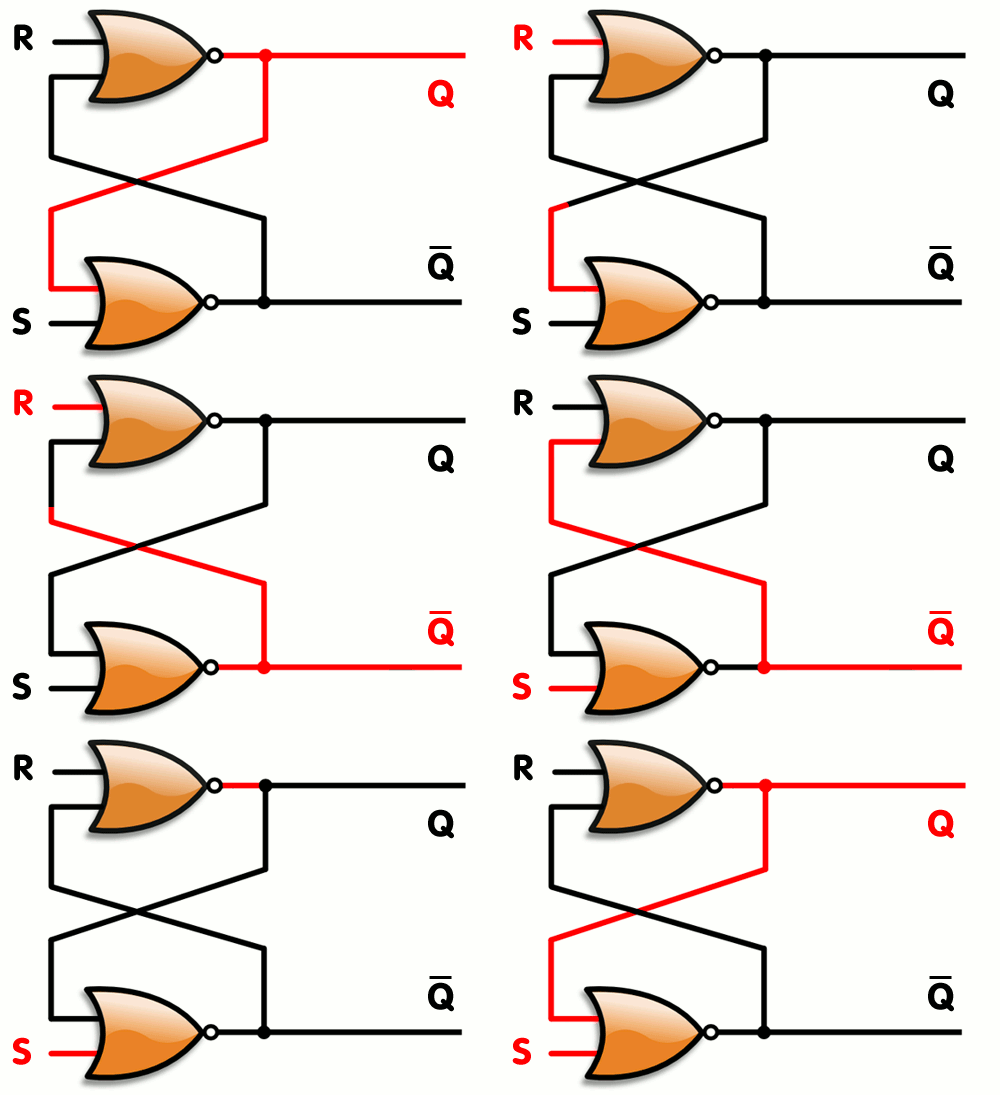
Model 3: The SR Latch
Questions
- The purpose of S is to set the output (Q) to high. R is a reset, and sets Q to low. Q bar is just the opposite of Q. If Q is set to high by setting S to high, why does Q remain high even when turning off the current to S? As a hint: notice that you aren't sure the output of the NOR gate following the R input, but since you know S must be 1, you do know its output. Use this to trace the rest of the circuit.
- What do you think is the purpose of an SR Latch?
- How can we cause an SR Latch to set when a series of conditions occur: for example, to unlock our door when it is warm and not raining outside?
Model 4: The 555 Timer
Questions
- When does the SR Latch get set to high, and when does it get set to low?
- How often does the Q state of the SR Latch oscillate?
- What controls the oscillation of the SR Latch?
- How might one determine the frequency of the timer? That is, what should the period of a timer or clock be when used inside a computer? Could you make the timer as fast as you want? Why or why not?
- What elements of the 555 Timer would you adjust to make the SR Latch oscillate faster or slower?
Model 5: DeMorgan's Law
A AND B
NOT (NOT A OR NOT B)
A OR B
NOT (NOT A AND NOT B) = (NOT A NAND NOT B)
(A NAND A) NAND (B NAND B)
NOT (NOT A OR NOT B)
A OR B
NOT (NOT A AND NOT B) = (NOT A NAND NOT B)
(A NAND A) NAND (B NAND B)
Questions
- Draw a truth table for the above logic formulas. What do you notice?
Reflective Journal Prompt
- What is the result of an input NAND itself? What might you call this gate?
- Considering that the AND of two inputs is the NOT of the NAND, use the NAND-based NOT gate above to create an AND gate.


